Torsion on Open Section Beams and Pipe Supports Design
In the last twenty years, with the increased use of 3D modelling in the O&G industry, most of the EPC companies have progressively passed the pipe supports selection and design duties from Stress Engineers and Pipe Supports Specialists to Piping Designers, who are directly involved in the 3D modelling. This handover has generally not been supported by a structured knowledge transfer, which has resulted in some recurrent examples of non-optimal design. This paper addresses one of them, specifically the effect of torsion induced on open shape beams, the implications of which are generally little known by the wider audience, by presenting the engineering problem, proposing the appropriate solutions for some typical cases and discussing some experimental results, in an effort to raise the overall awareness on the matter.
Introduction:
The present article is divided into three parts:
- Part A contains a simple mathematical dissertation on open shape beams subject to torsion
- Part B lists some of the typical torsion related issues in the pipe support design for the O&G industry. A solution to contain the effects of torsion is given for each case.
- Part C recounts about the findings of an experiment done at site.
General:
Steel beams have evolved across last centuries to respond to the changing needs of societies and technology; it has to be recognized that beams shapes have been developed by Mankind (not readily available as such in Nature) to resist specific type of loading and thus may not work properly when subjected to kind of loading different from the ones they have been engineered for.
Among the above ones, two of the most recurrent shapes, utilised in various Industries, for various scopes, are the circular hollow shape (pipe) and the H shape (HEA and UC beams in example), see Fig. 1.
This article will mainly focus on these shapes for illustrative purposes around the subject.

Fig. 1
PART A – Open shape steel beams under torsion
Torsion on beams: Twisting.
The change of rotation (twist) per unit length (i.e. the first derivative of rotation) of a St Venant beam subject to torsion (pure torsion of a long prism unrestrained at its ends) is given by the following formula:
ɸ’ = T/G IT , where
T is the applied torque
G is the shear modulus
IT is the St Venant torsional constant
The rotation ɸ of one end of the prism with respect to the other end is thus LT/G IT, where L is the length of the prism.

Fig. 2
Torsion on beams: Warping.
Warping happens when the sections of the prism are unable to keep flat during deformation (i.e. deformation of the section happens also in the X direction in Fig. 1 under loading). Warping depends on the shape geometry, round shapes do not develop warping during twisting while open shapes (all commercial profiles) generally develop some degree of warping, with the most significant effects being shown by H types profiles. If warping deformation is prevented by constraints (like i.e. welded or flanged connection at one end of the prism) then stresses arise which may be significant and need to be accounted for in the design. For the purpose of this sheet it is important to note that warping involves the development of deformations not symmetrical with respect to the loading (i.e. a support may not just twist but may develop movements in directions not coherent with the load direction).
A Simple Calculation
Note: this article focuses on the deformations experienced by open shapes when subjected to torsion and is aimed to assisting the designer in the selection of the best support arrangement to avoid the occurrence of torsion; as such, given that torsion in pipe support design is regarded as something to be eliminated rather than designed for, no mention of how to calculate stresses has been deliberately made. However part B is entirely derived from the SCI publication “Design of steel beams in torsion” 1: for a complete dissertation on the subject the reader may refer to the above mentioned publication or others included among the references. Let us consider now the case of an inverted L post on which an axial stop is installed (see Fig. 3) and calculate the rotation that occurs at member b as a result of twisting in member a.
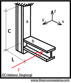
Fig. 3
Data:
Twisting length C of member a (from the intersection with member b CL to the top connection of the inverted L post)= 1400 mm
Lever arm L (from CL of load F to intersection between member a and b, measured along member b axis)= 700 mm
Force F (due to axial stop)= 1 kN
Shape designation (assumed same for member a and b) : UKC 152x152x23
Saint Venant torsional constant1: 4.63 cm4 = 4.63 x 10^-8 m4
Shear modulus (G)1 : 81 GPa = 81 GN/m2
Calculation:
Applied torque T: F x A = 10 kN x 0.7 m = 7000 Nm
ɸ’= T/G IT = 700 / (81000000000 x 0.0000000463) ≈ 0.19 Rad/m
Rotation (across the “a” member whole length C): 1.4 x 0.19 = 0.266 Rad = 0.266 x 360 / (2π) ≈ 15 ⁰
Horizontal movement at point of application of F load (along F axis) = 0.7 x sin 15⁰ ≈ 0.181 m
As it can be seen the result makes the choice of an H shape structure for this application totally unsuitable (the axial stop, often referred to as “fixed point”, would move nearly 20 cm).
If we had made the “a” member out of a cylindrical hollow shape the results would have been completely different as all the components of equation (1) would have been exactly the same apart from IT which, for a pipe of a similar size and linear weight (i.e. 139.7 x 6.3) would have been about 1180 cm4, leading to a movement of just 0.7 mm (generally acceptable for an axial stop).
This doesn’t want to be an exhortation to use cylindrical hollow shapes in support design, cause:
- They may often be rejected by Clients due to internal corrosion concerns
- They bring along the difficulty of shaping the contour of member b
however the above calculation shows how much more effective a closed circular shape is in resisting torsion with respect to an open one.
Note: the result above substantiates the use of plates fully welded along the “a” member so to turn the latter into a closed squared section (Fig. 4) and reduce its twisting (practice also known as “boxing” a shape); despite not a neat solution (high stresses may exist at the sharp edges where welding is performed and need to be evaluated) this solution may constitute a low impact highly effective last resort (addition vs modification) when loads are not significant and there might not be another easy ways through (i.e. inverted L post support already installed).

Fig. 4
Comparatively, from what has been explained in pictures and numbers within part A of this sheet, it can be inferred that the solution, sometimes proposed, of stiffening a support against torsion by simply adding the usual stiffening plates meant to reinforce the structures against concentrated loads (Fig. 5) is to be considered meaningless: member “a” will remain substantially unstiffened and will continue to show the same behaviour already analysed over the length C-t (being t the thickness of the stiffening plate); in other words the only considerable stiffening effect is introduced in principle just over a limited portion of the structure, comparable to the thickness of the added plate.
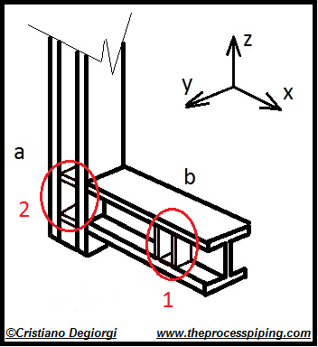
Fig. 5
The addition of plates at location 1 offers no contribution whatsoever to limiting the twisting of member “a”, being the plates placed symmetrically and in line with the load.
PART B – Pipe support induced torsion on beams: frequent examples in the O&G industry and their correct solution
This section discusses three typical examples of torsion occurrence at pipe supports installations and proposes the most appropriate line of action:
Axial stop on cantilever from columns or L post:
This is a frequent design often arising at fixed points locations on small bore lines, with the case shown on Fig. 6a (cantilever on a column) being less severe, in terms of induced displacements, with respect to the case shown in Fig. 6b (L post, having a free end). However, as we saw in the previous section, even very limited loads (i.e. 1 kN) can cause movements of a couple of order of magnitude greater than the expected ones at a fixed point hence the solutions on the left hand side of pictures 6 should only be used when the loads are negligible (note: as a first approximation the case of the cantilever can be studied as the mechanical parallel of the stiffness deriving from two L posts). In all other cases, when the loads cannot deemed negligible (i.e. inducing unacceptably large displacements), the solutions proposed on the right hand side of pictures 6 shall be pursued.
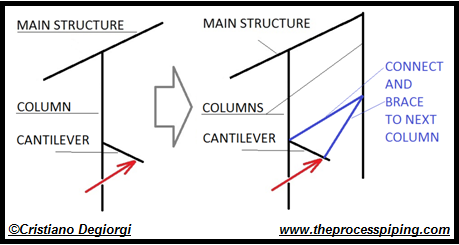
Fig. 6a
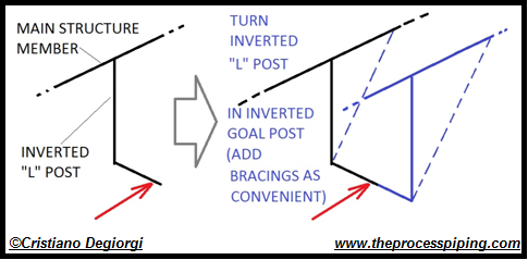
Fig. 6b
Vertical support offset from main structure:
This is a relatively frequent case that arises when a line is supported outside a platform and from the platform steel itself. The direction of the beams supporting the grating may not protect against the torsional effects shown in the left hand side part of picture 7a. Also in this case the vertical displacements may be significant and a connection to an adjacent beam is always recommended to turn the torsion into bending as much as possible (the beam will still be subject to torsion but this will be significantly limited, in terms of overall rotation at the cantilever, by the relative deflections allowed by the two members interested by the loads shown by light blue arrows on the right hand side picture of Fig. 7a).
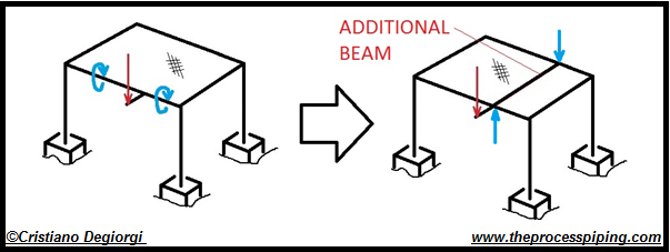
Fig. 7a
A similar case often arises when small bore lines are routed around a building perimeter and supported from the building cladding structure. Small bore lines can normally only span a fraction of the distance between the building columns, however, it has to be recognised that providing one (or more) cantilever from an horizontal beam belonging to the cladding structure (see Fig. 7b) will not offer an effective mean of support as, unlike where in coincidence with the building columns, relatively large rotations will occur meaning that a significant transfer of load will concern the cantilevers installed in coincidence of the main columns and, likewise, that the deflections at the mid span cantilevers will likely exceed the permissible ones. Again, also in this case, as a minimum, a vertical connection to a parallel member either above or below the one subject to torsion shall be considered so to turn torsion into bending and limit the overall deflections (ref. to Fig. 7a).

Fig. 7b
Axial stop lugs engaging the top flange only of a support beam:
This typical design issue refers to an axial stop, often referred to as a “fixed point” or, improperly, as an “anchor”, where the axial movement of a pipe is prevented by welding lugs to the underneath of the pipe support so to engage the beam.

Fig. 8a
The case in subject has to be referred generally to large bore lines, normally “stopped” against primary structural members, discharging relevant loads (typically in the range of hundreds of kN). In this case the concern is not primarily the displacement arising from the beam deformation but the beam stresses, particularly at the beam connections, which may not be designed for this kind of loading.
Fig 8a (right hand side) shows the solution that should be the first line of action for limiting the occurrence of torsion in the structural member. However this solution may not sometimes be practicable, either due to geometry reasons (i.e. very deep H shapes that would challenge the strength of the stop lugs, which size is normally to be contained within the standard support length) or due to the magnitude of the loads; in all such cases consideration should be given to decoupling the rest and stop function as shown in Fig. 8b, in consultation with the relevant structural design function.
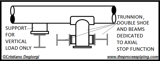
Fig. 8b
PART C – Experimental evidence
This part summarizes the findings from an experiment conducted at site, aimed at demonstrating the unsuitability of an inverted L post as a mean to protect sensitive equipment. The axial stop shown in Fig. 9 was meant to protect one reactor feed pump; the pump nozzle verification was just satisfied under the hypothesis of infinitely rigid restraint (i.e. L post not to move appreciably under the stop load), which, as we will see, was far from being satisfied by the inverted L post.
L post data (ref. Fig. 3,9): C = 1.4 m; L = 0.75 m; F = 500 Kg; Shape: HEA140.
Note: Fig. 9 shows the stop lugs not in contact with the L post; this is because the lugs are normally tack welded in the shop to the shoe in order not to get lost in field. Final repositioning at site during erection had still to take place at the time the experiment was conducted.
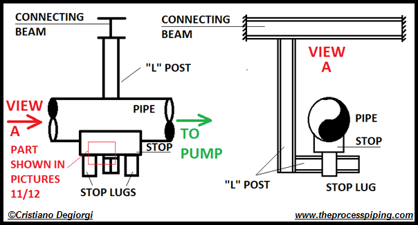
Fig. 9
The experimental set-up shown in Fig. 10 was put in place so to create a horizontal pull of 125 Kg (approx.) and demonstrate that the support was not suitable to withstand the half a ton load it was meant to withstand from the pipe stress calculation.

Fig. 10

Fig. 11
Fig. 11 shows clearly that the 125 Kg load induced a so large displacement of the structure that its movement was only eventually limited by the contact with the stop lug. The stop didn’t move appreciably as it was already tightened onto the process line which, in turn, was anchored to the pump nozzle. In Fig. 12 it is possible to see that the horizontal displacement of the inverted “L” post load application point was about 9.6 cm before that contact with the axial stop was reached.

Fig. 12
Note 1: the fact that the travel of the inverted “L”post horizontal member was eventually limited by the presence of the axial stop means that the actual total displacement caused by the load is unknown (we only know that the displacement would have been larger than 9.6 cm). This however was in line with the purpose of the experiment and is in line with the aim of the current paper: torsion on secondary structures where industrial pipe supports are installed is generally to be prevented rather than considered in the design.
Note2: The clamped axial stop was considered as a fixed point in the experiment as the line movement caused by the application of a 125 Kg load would have only been in the range of few mm and the aim of the experiment was just to show that the secondary structure was far from being able to take a load 4 times larger than the experiment one without moving appreciably. As such a flexible meter was laid on to the axial stop bottom plate so to track the member movement. The result is shown in the picture 12.
Note 3: from Fig 11 it is possible to notice that the metallic rope was tied to the inverted “L” post horizontal beam in a way that caused the load to be transferred mainly though the top flange. Furthermore, because of the presence of the axial stop itself the load was applied alongside the edge of the pipe support. This was not intentional and was due to how the experimental setup was erected. The reader is cautioned about these two misalignments with respect to the actual loading that would have arisen from the axial stop (i.e. no rotation of the horizontal member due to the lugs engaging both flanges and load in line with the axial stop centre line), however the purpose of the experiment was only to show that the stiffness of the support assembly was not in line with the hypothesis made in the stress calculation.
Note 4: it shall be noted that the inverted goal post was welded at the top to an HE200A beam, subject to torsion as well. The entire assembly stiffness against a horizontal force was so low that a movement of few mm of the L post lower part could be achieved just by pushing it with one finger.
The inverted “L” post was eventually reinforced by means of double bracing and the pump entered operation safely. If the experiment hadn’t been carried out the pump would have almost certainly failed in a short time (this kind of issues cannot be captured during pump alignment).
Conclusion
The unsuitability of open shape members to resist torsional moments was demonstrated through a simplified calculation (Part A) and the presentation of experimental evidence (part C). The conclusion form this paper is that torsion shall be “designed out” of industrial piping support assemblies; a series of examples of how this can be achieved in typical situation was illustrated in part B.
References:
- A F Hughes, D C Iles, A S Malik (2011). Design of steel beams in torsion, SCI Publication P385. ISBN 13: 978-1-85942-200-7.
- Crandall, Dahl, Lardner (1959). An Introduction to the Mechanics of Solids. Boston: McGraw-Hill. ISBN0-07-013441-3.
Cristiano Degiorgi (FLUOR ltd), is a master degree qualified Chartered Mechanical Engineer with a 18 years experience in industrial piping stress analysis and pipe support design. As a consultant he has spent more than 2 years at various sites, involved in the successful rectifications of capital piping systems, one of the activities he appreciates most along with the enhancement of procedures and working methods. Cristiano voluntarily contributes to the development of the Engineering Profession under the IMechE Monitored Professionals Development Scheme, as a Mentor, since 2015.