Introduction to Valves
Various types of valves are required in any piping system in order to regulate the fluid flow within that system. Valves can be manually operated or they can have an actuator to change and control the valve opening. The actuator may be pneumatically, hydraulically, or electrically operated. The valves represent a considerable percentage of the overall expenditure of the chemical process industry and, therefore, must be carefully selected.
Valves are installed on equipment/piping to perform any of the following functions,
- Isolation
- Reglation
- Non Return
- Special Purpose
It is imperative that process piping engineer should be familiar with all types of valves and the advent of any new designs. Thorough knowledge of the operation, maintenance, and adjustment of valves is equally important since the success of the process plant and its total activity will depend on it. In this article we are going to study the overview of few most common valves used for isolation and regulation purpose. These include the gate valve, globe valve, needle valve, butterfly valve, ball valve, plug valve, and check valve.
Gate Valves
The gate valve, shown in Fig. 1, consists of a gate-like disc, actuated by a screwed stem and handwheel, which moves up and down at right angles to the path of flow. In the closed position, the disc seats against two faces to shut off the flow. Gate valves are not suitable for throttling service because excessive wear, due to wire drawing (erosion), occurs on the gate and gate seats. They are suitable as stop (or isolating) valves, where conditions require either full flow or no flow. They have the advantage that, when fully opened, the resistance to flow is low with a minimum of pressure drop, as the fluid flow moves in a straight line.
Figure 1
Gate Valve

Globe Valves
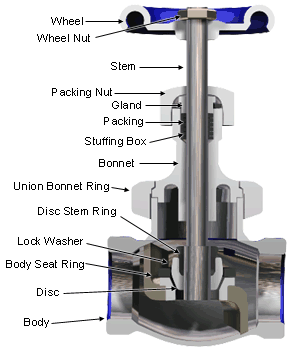
The globe valve, shown in Fig. 2, is constructed in such a way as to cause the flow of the fluid passing through it to change direction twice. The disc and the seat are parallel to the main flow path, and the disc is moved toward, or away from, the seat by means of a threaded stem. Due to its construction, the globe valve is ideal for throttling or regulating flow with a minimum of wire drawing and seat erosion. Another advantage of the globe valve compared to the gate valve is that it is cheaper to manufacture. On the other hand, the globe valve offers much more resistance to flow than does the gate valve. The unbalanced single disc type of globe valve shown in Fig. 2 is seldom used in sizes larger than 305 mm (12 in.) due to difficulty in opening and closing against fluid pressure.
Figure 2
Globe Valve
Needle Valves
Needle valves, shown in Fig. 3, are designed to allow precise flow control. Its name is derived from the sharp pointed disc and matching seat. They are extensively used for continuous blowoff or chemical feed control services. The stem threads are finer than usual so that considerable movement of the hand wheel is required to increase or decrease the opening through the seat. Usually, these valves have a reduced seat diameter in relation to the pipe size.
Figure 3
Needle Valve

Butterfly Valves
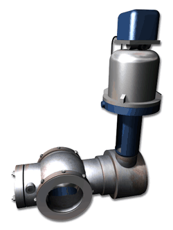
A butterfly valve, shown in Fig. 4, consists of the valve body, disc, shaft, and the necessary packing and bushings for shaft support. The body is frequently a solid ring type, which is mounted between pipe flanges. The disc is generally cast in one piece. Correct alignment of this valve is required to prevent binding of the swing-through disc. The thickness of the disc is determined by the pressure drop across the valve (throttling or closed position). Butterfly valves come in sizes from 25 to 3800 mm (1 to 152 inches) and are designed for pressures up to 13 800 kPa and temperatures up to 1100ºC. The flat disc can be rotated through 90º from the wide open to the fully closed position. The valve is fitted with a lever for manual operation. A power actuator is required to position the disc for bigger sizes because large pressure differentials can exist across the disc. The valve shown in Fig. 5 can be manually or electrically operated. The butterfly valve is commonly used in thermal and hydroelectric power stations, oil and gas processing industries, oil and gas transmission, and in water and sewage plants. They have the following advantages: relatively light weight, ease of operation, self cleaning, and negligible pressure drop across the valve when it is fully open.
Figure 4
Butterfly Valves

Figure 5
Power Operated Butterfly Valve

Ball Valves
The ball valve, shown in Fig. 6, contains a spherical plug with a passage bored through it which controls the fluid flow through the valve body. The basic type of ball valve requires a quarter turn from the fully open to the fully closed position. The valve can be operated by means of a lever, which also serves as an open or shut indicator, or by the use of an automatic actuator.
Figure 6
Ball Valve

The spherical plug not only gives precise control of the flow through the valve, but also gives a tight shutoff when in the closed position. The valves are designed so that no internal lubrication is required and the torque required to rotate the ball is negligible. The ball and stem are generally machined from one piece.
For larger sizes and higher pressure ratings, the ball is constructed with a double stem and is supported by bearings. This construction requires a seal for one end and a packing box for the opposite end. Fig. 7 shows such an arrangement.
Figure 7
V Ball Valve

Fig. 8 illustrates the alternative manual-automatic operation for this particular valve. The ball valves are manufactured in sizes from 3 to 1000 mm (1/8 to 40 in.) and for pressures up to 69000 kPa with service temperatures from -185ºC to 550ºC.
Figure 8
Manual-Automatic Positioning

Ball valves are suitable for handling slurries and fluids with a high solid content, and for this reason have found wide applications in the paper industry, chemical plants, and sewage treatment plants.
Plug Valves
The plug valve, shown in Fig. 9, is a quarter turn valve, as are butterfly and ball valves. The plug valve consists of a tapered or straight cylinder containing a hole, which is inserted into the cavity of the valve body. The hole in the plug lines up with the axis and opening in the valve body. The valve has a tapered plug which is secured in the valve body by the valve cover. A packing box is recessed in this cover, with packing held in place by the gland, thus preventing leakage along the valve stem.
Figure 9
Plug Valve

The tapered plug has a tendency to jam in the tapered seat and can cause scoring if forced to turn. Most plug valves are lubricated to eliminate this problem. The lubricant is supplied through the center of the stem and is distributed through channels to the seating surfaces. Other valves are equipped with a flexible, smooth liner which eliminates the need for
lubrication. The pressure drop across this valve when it is in the wide open position is very low. This type of valve is self-cleaning. Plug valves are used as quick opening valves in gas supply lines, low pressure steam lines, water treatment plants, pulp and paper, and chemical industries.
Check Valves
The check valve, shown in Fig. 10 and Fig. 11, is a valve which prevents reversal of flow in piping. The flow of fluid keeps the check valve open while gravity and reversal of flow will cause the valve to close. The two basic types of check valves are the swing check and the lift check.
Figure 10
Swing Check Valve

Figure 11
Lift Check Valve

The swing check valve features an almost straight line flow, and therefore offers little resistance to flow. The disc, which is hinged at the top, swings freely in an arc from the fully closed to the fully open position. The flow through the lift check valve undergoes two changes in direction as it passes through a horizontal section upon which the disc seats. The disc moves upward to allow the fluid to pass through and moves downward to close if the flow should reverse. A dashpot is used to
cushion the action of the disc in this design.
a technical knowledge base for all the process piping professionals around the world…
